5G Signalling Procedures Part-3 Updated In 2024
Introduction To 5G Signalling Procedures

As 5G technology continues to evolve, understanding the critical 5G signalling procedures within the 5G Radio Access Network (RAN) becomes increasingly important. This blog delves into the RRC (Radio Resource Control) Connection Setup procedure, a fundamental aspect of the 5G signalling Procedures process that facilitates the transition from RRC Idle mode to RRC Connected mode. This transition is essential for enabling application data transfer and other signalling procedures in a 5G environment.
RRC Connection Setup In 5G Signalling Procedures
- The RRC Connection Setup procedure is used to make the transition from RRC Idle mode to RRC Connected mode. The UE must make this transition before transferring any application data, or completing any signalling procedures.
- The RRC_Connection Setup procedure is always initiated by the UE but can be triggered by either the UE or the network. For example, the UE triggers RRC Connection Setup if the end-user starts an application to browse the internet, or to send an email. Similarly, the UE triggers RRC Connection Setup if the UE moves into a new Tracking Area and has to complete a Tracking Area Update. The network triggers the RRC Connection Setup procedure by sending a Paging message. This could be used to allow the delivery of an incoming SMS or notification of an incoming voice call.
- The RRC Connection Setup procedure configures Signalling Radio Bearer (SRB) and allows subsequent signalling to use the Dedicated Control Channel (DCCH) rather than the Common Control Channel (CCCH) used by SRB 0. The initial Non-Access Stratum (NAS) message is transferred to the Base Station as part of the RRC Connection Setup procedure. The Base Station subsequently forwards this message to the AMF.
- The signalling for the RRC Connection Setup procedure is shown in Figure below. It is based upon a 3-way handshake between the UE and Base Station. This figure also illustrates the initial NAS message being forwarded to the AMF.
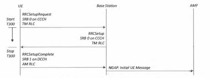
- The RRC Setup Request is sent on the PUSCH as MSG3 during the contention based Random Access procedure. It is transferred using SRB 0 on the Common Control Channel (CCCH) because SRB 1 has not been established at this stage. The Resource Block allocation for the RRCSetupRequest is provided within the Random Access Response message (MSG2).
- The content of the RRCSetupRequest is shown in Table below. lt includes a UE identity and an establishment cause. There is no scope for the UE to report any measurements within the RRCSetupRequest. In contrast, the UMTS (3G) version of the RRCConnectionRequest allows the UE to report CPICH measurements which can be used for open loop power control calculations.

- The content of the RRC Setup Request has been carefully specified to limit the message size to 48 bits. In general, it is important for MSG3 to be small because it cannot be segmented, i.e. it is transferred using Transparent Mode RLC which does not support segmentation. The payload illustrated in Table above indicates a message size of 39 bits for the UE identity plus 4 bits for the establishment cause (there are 10 cause values which can be encoded using 4 bits). This generates a total of 43 bits. 3GPP TS 38.331 also specifies 1 ‘spare’ bit within the payload which is not shown in Table above. In addition, it is necessary to include 1 bit to signal the choice between the two types of UE identity. Similarly, it is necessary to include 2 bits to signal the choice between four potential CCCH messages: {RRCSetupRequest, RRCResumeRequest, RRCReestabfishmentRequest, RRCSystemlnfoRequest}. Finally, 1 bit is included to signal the choice between the existing set off our CCCH messages and a message extension which can be used lo introduce new messages in the future.
- The UE adds an 8 bit MAC header to the RRCSetupRequest so the total message size is 48 + 8 = 56 bits. It should be noted that this corresponds to the smallest value that can be configured for ra-Msg3SizeGroupA. This means that the UE always selects a ‘Group A’ PRACH preamble when sending an RRCSetupRequest (this statement is applicable when the Base Station configures ‘Group A’ and ‘Group B’ PRACH preambles, otherwise the message size does not impact the preamble selection procedure).
- If the UE has already registered with the 5G Core Network using a previous RRC Connection, and the AMF has already allocated a 5G-S-TMSI then the UE identity within the RRCSetupRequest can be signalled using the 39 least significant bits from the 5G-S-TMSI. The 39 least significant bits include the 5G TMSI, the AMF Pointer and 1 bit from the AMF Set Identity. The complete 5G-S-TMSI is not included within the RRCSetupRequest because it would make the message size too large. The set of 39 bits are sufficient to minimise the probability of multiple UE using the same UE identity. The remaining 9 bits can be included within the RCSetupComplete message. Otherwise, the UE populates the UE identity field with a random number within the range 0 to 239.
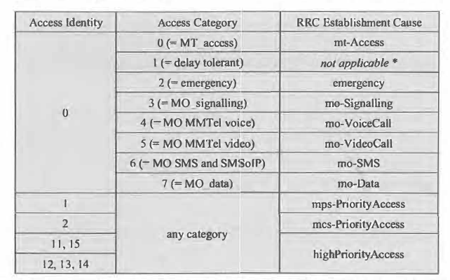
- The establishment cause within the RRC Setup Request is selected using a mapping which is based upon the combination of Access Identity and Access Category. Table below presents this mapping for a New Radio (NR) Base Station connected to the 5G Core Network. 3GPP TS 24.501 specifies a second mapping for an EUTRA Base Station connected to the 5G Core Network.
- The UE starts the T300 timer after transmitting the RRCSetupRequest. The value of T300 is broadcast within SIB 1. The RRC Connection Setup procedure fails if T300 expires before the UE receives the RRC Setup message. The RRC layer docs not support re transmissions of MSG3 within a specific connection setup attempt. However, HARQ re-transmissions of MSG3 can be triggered at the MAC layer while T300 is running. The Base Station triggers HARQ re-transmissions of MSG3 using DCI Format 0_0 to provide a new uplink resource allocation on the PUSCH. The CRC bits belonging to the DCI arc scrambled using the Temporary C-RNTI. The Contention Resolution timer is re-started after a HARQ re-transmission ofMSG3, but T300 is not re-started.
- Random access contention can occur after sending the RRCSetupRequest. Contention occurs when multiple UE select the same PRACH occasion and the same PRACH preamble. Contention requires the UE to repeat transmission of the PRACH preamble and the subsequent RRCSetupRequest. This increases the delay associated with connection establishment but does not cause the overall procedure to fail unless the maximum number of preamble transmissions has been reached.
- The Base Station can multiplex the RRC Setup message within the same PDSCH transmission as the ‘UE Contention Resolution Identity’ MAC Control Element. The RRC Setup message is transferred using SRB O on the downlink CCCH. The RRCSetup message provides configuration information for SRB 1. This allows subsequent signalling to use the Dedicated Control Channel (DCCH). SRB 2 is always configured after security activation so the RRC Setup message does not include any information regarding SRB 2.
- Table below presents the high level content of the RRCSetup message. The message is divided into two main sections: Radio Bearer configuration and Master Cell Group configuration. The Radio Bearer configuration provides information regarding the PDCP layer, whereas the Master Cell Group configuration provides information regarding the RLC, MAC and Physical layers. This structure is particularly useful when using the Centralised Unit (CU) Distributed Unit (DU) split Base Station architecture because it allows the CU to generate the Radio Bearer configuration and the DU to generate the Master Cell Group configuration.
- The RLC layer configuration links a logical channel identity to the SRB identity. It also provides the RLC configuration (only shown as rlc-Config within Table below). The RLC configuration specifies the set of Acknowledged Mode RLC parameters for SRB 1, e.g. uplink and downlink Sequence Number lengths, maximum number of re-transmissions, re-assembly timer and Status Report polling configuration. The mac-LogicalChannelConfig provides uplink prioritisation information to ensure that SRB 1 is prioritised appropriately relative to other logical channels.
- The MAC layer information can be used to configure Discontinuous Reception (DRX), Scheduling Requests, Buffer Status Reporting (BSR), Timing Advance Groups {TAG) and Power Headroom (PHR) reporting. The Physical layer configuration can be used to provide information regarding HARQ acknowledgements and power control. It can also be used to allocate RNTI values (other than the C-RNTI which has already been allocated during the Random Access procedure).
- The Master Cell Group configuration also provides the Special CelI (spCell) parameter set which includes the spCellConfigDedicated parameter structure. This relatively large parameter structure configures the PDCCH, PDSCH and PUSCH in combination with other parameters linked to the serving cell.
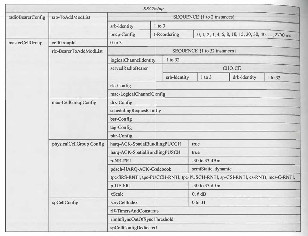
RRC Setup Message
- Upon receiving the RRC Setup message, the UE stops the T300 timer and makes the transition to RRC Connected mode. The UE then requires an uplink resource allocation to transmit the RRC SetupComplete message on the PUSCH. This requires the UE to send a Scheduling Request unless the Base Station provides a proactive grant. After receiving the uplink resource allocation on the PDCCH, the UE is able to transmit the RRCSetupComplete. The content of the RRC Setup Complete is shown in Table below.
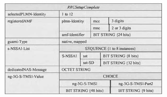
- The selected PLMN identity defines a pointer to a PLMN listed within SIBI, i.e. the UE selects a PLMN for its connection request when a cell belongs to more than a single PLMN.
- The Single Network Slice Selection Assistance Information (S-NSSAI) allows the UE to request a specific set ofNetwork Slices. Each Network Slice is specified in terms of its Slice/Service Type (SST) and Slice Differentiator (SD). The UE is permitted to request up to 8 Network Slices.
- Inclusion of the registered AMF and the requested Network Slices helps the Base Station to select an appropriate AMF for the UE’s signalling connection towards the 5G Core Network.
- The UE also includes its initial Non-Access Stratum (NAS) message within the RRCSetupComplete. NAS messages arc specified within 3GPP TS 24.50 1. Example initial NAS messages include Registration Request, De-registration Request and Service Request.
- The final part of the RRCSetupComplete provides the 9 Most Significant Bits belonging to the 5G-S-TMSI {the 39 Least Significant Bits were already provided within the RRCSetupRequest (assuming a SG-S-TMSI has already been allocated to the UE). The RRCSetupComplete also supports the inclusion of a complete SG-S-TMSI but this option is not used if the UE has sent an RRCSetupRequest (it can be used if the UE has received an RRCSetup in response to a RRCResumeRequest).
- The Base Station extracts the NAS message from the RRCSetupComplete and forwards it to the appropriate AMF using the NG Application Protocol (NGAP) Initial UE Message. Forwarding this message does not form part of the RRC Connection Setup procedure but is described in this section for completeness. The content of the NGAP Initial UE Message is shown in Table below.
- The Base Station allocates the ‘RAN UE NGAP Identity ‘to allow the Base Station to identify the UE within NGAP signalling procedures. The ‘AMF UE NGAP Identity’ (not included within the Initial UE Message) allows the AMF to identify the UE within NGAP signalling procedures.
- The ‘User Location Information’ specifies the location of the UE in terms of Cell Global Identity (CGT) and Tracking Area Identity {TAI). The ‘RRC Establishment Cause’ is set equal to the cause value within the RRCSetupRequest.
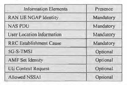
- The ‘AMF Set Identity’ is included if the NGAP: Initial UE Message has been re-routed. The AMF selected by the Base Station may determine that it cannot support the UE, e.g. due to not supporting the set of requested Network Slices. In this case, the AMF may forward the initial NAS message directly to another AMF. Alternatively, the AMF can return the initial NAS message to the Base Station within an NGAP: Reroute NAS Request. This message provides the Base Station with a new target AMF Set Identity and a corresponding set of Allowed NSSAI (which are then also included within the NGAP: Initial UE Message when it is re-routed).
- The NGAP Initial UE Message can also include a ‘UE Context Request’ flag to indicate that the Base Station would like the AMF to start the Initial Context Setup procedure.
Handling RRC Setup Rejections
- Figure below illustrates the signalling associated with the RRC Connection Setup procedure when the Base Station rejects the RRCSetupRequest. The reject message is returned to the UE using SRB 0 on the CCCH logical channel. The Base Station may reject the connection establishment request as a result of congestion.

- The content of the RRCReject message is presented in Table above. lnclusion of the waitTime is optional so the Base Station may send in empty message. If the wait time is included, the UE starts timer T302 with its expiry value set equal to the wait time. With the exception of Access Categories 0 and 2, all connection attempts are access barred until T302 expires. Access Categories 0 and 2 correspond to mobile terminated access and emergency access respectively. In the case of mobile terminated access, the network is responsible for controlling access by preventing the transmission of paging messages if necessary. T302 is stopped if the UE completes cell re selection so in that case, the UE is permitted to attempt an RRC Connection Setup with the new serving cell.

Centralised Unit (CU) and Distributed Unit (DU) Split Base Station Architecture
- Figure below illustrates the RRC Connection Setup procedure assuming a Centralised Unit (CU) Distributed Unit (DU) split Base Station architecture. This architecture requires FI Application Protocol (FIAP) signalling between the CU and DU.

- The RRCSetupRequest is forwarded to the CU using an Fl AP: Initial UL RRC Message Tram/er. This Fl AP message is shown in TabIt: 343. The DU allocates the ‘gNB-DU UE fIAP Identity’ to allow the DU to identify the VE within subsequent FIAP signalling messages. The Cell Global Identity (CGI) is included to allow that: CU to forward it to the AMF within the NGAP: Initial UE Message (part of the ·user Location Information’). The DU also specifies the C-RNTI which has been allocated to the UE during the Random Access procedure.
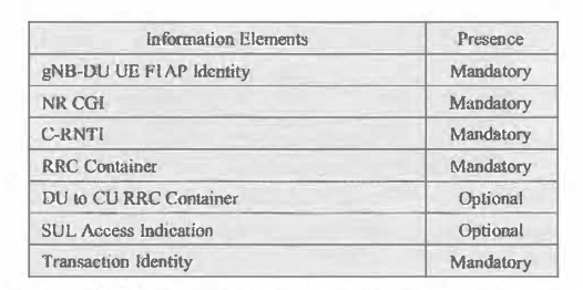
- The ‘RRC Container’ encapsulates the RRCSetupRequest received from the UE. The DU to CU RRC Container’ provides the CU with the CellGroupConfig parameter structure which the CU subsequently uses to generate the masterCellGroup section of the RRCSetup message, i.e. the CU hosts the RRC layer and is responsible for generating the RRCSetup message but some of the content originates from the DU.
- The ‘SUL Access Indication’ is used as a flag to specify that the UE has accessed the cell using a Supplemental Uplink carrier.
- The ‘Transaction Identity’ is used to differentiate between all ongoing parallel procedures of the same type.
- The FIAP: DL RRC Message Transfer includes the gNB-DU UE FIAP Identity’ allocated by the DU. and also a ‘gNB-CU UE FIAP Identity’ allocated by the CU. The FI AP message also specifies the SRB associated with the encapsulated RRC message. In the case of the RRCSetup, this is always SRB 0. The DU can use this information to generate the MAC header which includes the Logical Channel Identity (LCID). The FIAP message can also request the DU to provide an RRC Delivery Status report for the downlink transmission. The Fl AP: RRC Delivery Report provides the highest in-sequence successfully delivered PDCP Sequence Number in combination with the PDCP Sequence Number of the downlink RRC message for which the report is generated.
- The Fl AP: UL RRC Message Transfer includes the SRB Identity and the encapsulated RRC message. It does not include any other fields except for the ‘gNB-DU UE FIAP Identity’ allocated by the DU, and the ‘gND-CU UE FIAP Identity’ allocated by the CU.
Conclusion
The RRC Connection Setup procedure is a fundamental component of 5G signalling, ensuring that the UE can transition from RRC Idle mode to RRC Connected mode to enable data transfer and other signalling procedures. As 5G technology continues to advance, understanding these procedures is crucial for maintaining efficient and reliable network operations.
References
- 4G 5G Testing and protocol analysis
- Syllabus for 4G 5G Protocol Testing Training
- Contact Us for training
- Qualcomm Academy Videos
- 3GPP Website
- ShareTechNotes


Comments
Post a Comment