5G RADIO NETWORK PLANNING PART-8 UPDATED IN 2024
Introduction To 5G Radio Network Planning
5G Radio network planning has evolved to accommodate the growing demands for faster and more reliable wireless communication. In this updated guide for 2024, we delve into the intricacies of 5G Radio Network Planning, with a focus on Cell and Base Transceiver Station (BTS) Identification, RAN Notification Area Planning, and Tracking Area Planning. As we explore these key aspects, we’ll discuss how to efficiently manage network resources, optimize cell throughput, and ensure seamless connectivity for end-users. This guide also highlights the importance of strategic planning to balance the trade-offs between signaling load, paging load, and mobility updates in the increasingly complex landscape of 5G deployment.
Cell & BTS Identify Planning In 5G Radio Network Planning
- Cells are identified at a global level using their NR Cell Global Identity (NCGI)
- the Mobile Country Code (MCC) and Mobile Network Code (MNC) uniquely identify the operator’s network
- the NR Cell Identity (NCI) uniquely identifies a cell within the operator’s networK.
- The NCGl and NCI structures are illustrated in Figure below

- The NCI has a total size of 36 bits.These 36 bits are shared between the gNB Identity and the Cell Identity. The gNB Identity can be configured to use between 22 and 32 bits. This leaves between 14 and 4 bits for the Cell Identity.
- Allocating 22 bits for the gNB Identity provides a range from 0 to 4 194 304. This range is likely to be sufficient for the majority of networks. Networks which include large numbers of small cells and/or Femto cells may require a larger gNB Identity range. Identities can be allocated to allow certain information to be deduced from the allocated value. For example, values 0 to 50 000 could be used for macrocells, white values 50 001 to 250 000 could be allocated for Femto cells.
- Within the context of the RRC Inactive state, there may be some benefit in restricting the number of bits used by the gNB Identity, e.g. using only 16 bits and setting the remaining bits to ‘0’. The RRC Inactive state relics upon the I-RNTI to identify both the Base Station which hosts the UE context, and the UE within that Base Station. The full I-RNTI has a length of40 bits, while the short I-RNTI has a length of24 bits. If16 bits within the I-RNTI are used to identify the Base Station which hosts the UE context, and ifonly 16 bits have been used within the gNB Identity, then the gNB Identity can be used directly within the 1-RNTI. This helps to avoid the requirement to plan additional Base Station identities specifically for the RRC Inactive state
- Allocating 22 bits for the gNB Identity allows 14 bits to be used for the Cell Identity. These 14 bits provide a range from 0 to 16 383 to identify a cell belonging to a specific Base Station. It is unlikely that a single Base Station will support this number ofcells although the number of cells per Base Station can become high when using the Centralised Unit (CU) / Distributed Unit (DU) Split Base Station architecture, e.g. a single Centralised Unit may support 150 Distributed Units and each Distributed Unit could support 6 or more cells.
- The Cell Identity can be allocated to allow certain information to be deduced from the allocated value. For example, the first 3 bits could be used to identify the sector, the next 3 bits could be used to identify the carrier and the remaining 8 bits could be used to identify the Distributed Unit (if using the CU/DU Split Base Station architecture).
- The MCC, MNC and NCI arc broadcast within SIB 1 (see Table 147 in section 6.2). The structure of SIB 1 allows a single channel to support multiple PLMN Identities (MCC/MNC) and multiple Cell Identities (NCI). This approach provides additional flexibility for network sharing deployment scenarios. It means that each operator can independently plan its own Cell Identities.
RAN Notification Area Planning
- Enabling the RRC Inactive state requires:
- The definition of RAN Notification Areas (RNA)
- The allocation of Base Station identities which can be included within the 1-RNTI
- The RRC Inactive state and RAN Notification Areas are described.
- A RAN Notification Area defines the area within which a UE can move while RRC Inactive without having to inform the network that the best serving cell has changed. The network docs not have knowledge of the UE location within the RNA so paging messages must be broadcast by all cells belonging to the RNA. The Base Station which released the UE to RRC Inactive hosts the UE context, the NG signalling connection towards the AMF and the GTP-U tunnel towards the UPF. The UE context is retrieved and the Core Network connections are moved if the UE returns to RRC Connected Mode using a different Base Station
- In 5g radio network planning a large RNA provides benefits in terms of reduced signalling load due to UE mobility, i.e. the UE is less likely to cross an RNA boundary and be required to send an RRCResumeRequest message to complete an RNA update procedure. A small RNA provides benefits in terms of reduced paging load.
- A small RNA also benefits from requiring fewer Xn connections although the requirement for Xn connections depends upon the Base Station architecture. If using the Centralised Unit (CU) Distributed Unit (DU) Split Base Station architecture then an RNA can include a large number of cells belonging lo a single Base Station, i.e. a large number of cells can be hosted by a single Centralised Unit. ln this case, the RRC Inactive state can be used with a minimal requirement for Xn interfaces.
- A RAN Notification Area can be configured as:
- A collection ofCell Identities, or
- A collection of Tracking Area Code (TAC) and RAN Area Code (RAC) combinations
- In both cases, it is necessary to identity RNA boundaries. A simplistic solution could be based upon allocating each Base Station to a separate RNA. In the case of the CU/DU Split Base Station architecture, this could result in more than 100 cells belonging to each RNA. In the case of the classical Base Station architecture, this could result in only 3 cells belonging to each RNA.
- In general RNA boundaries should avoid crossing high mobility routes to help minimise the requirement for RNA updates due to mobility. A single RNA could be planned to include all cells within a town centre, or all cells providing coverage lo a sports stadium
- An 1-RNTI is allocated to a UE when it moves to the RRC Inactive state. This 1-RNTI identifies both the UE and the Base Station which hosts the UE context. 3GPP supports both a full 1-RNTI which occupies 40 bits and a short T-RNTI which occupies 24 bits. The short T-RNTI is relatively restrictive in terms of the number of bits available to identify both the Base Station and UE but it minimises the size of the RRCResumeRequest message, i.e. it helps to maximise the coverage performance of MSG3
- The allocation of Base Station identities which can be included within the1-RNTI will depend upon the network implementation and the existing strategy for defining the gNB Identity within the NR Cell Identity. For example, if 16 bits from the full 1-RNTI are used to identity the Base Station, and if the gNB Identity within the NR Cell Identity has been allocated using only 16 bits, then those 16 bits can be copied and directly inserted into the 1-RNTI. This example scenario is illustrated in Figure below.

- 3GPP specifies the total size of a full and short I-RNT but does not specify the number of bits which are used to identify the Base Station (the allocation of 16 bits within Figure above is only an example)
- If a solution similar to that shown in Figure above is not adopted then it may be necessary to generate a second Base Station identity specifically for the purposes of the I-RNTI and the RRC Inactive state.
Tracking Area Planning
Networks based upon the EN-DCN on Standalone Base Station architecture do not require 5G Tracking Areas. UE use LTE for RRC Idle mode so UE extract the 4G Tracking Area Identity from the LTE SIB1. This Tracking Area is used for registration with the MME
- Networks based upon the Standalone Base Station architecture require 5G Tracking Areas. In this case, UE use NR for RRC Idle mode so UE extract the 5G Tracking Area Identity from the NR SIB 1 . This Tracking Area is used for registration with the AMF. The UE reports its current Tracking Area within the NAS: Registration Request message. The AMF is permitted to provide the UE with a list of Tracking Area Identities within the NAS: Registration Accept message. Including more than a single Tracking Area Identity allows the UE to roam outside the current Tracking Area without triggering a Tracking Area update procedure.
- The release 8 version ofLTE. allows SIB I to broadcast up to 6 PLMN Identities for the purposes of Network Sharing but all PLMN share the same Tracking Area Code (TAC) and the same Cell Identity. The release 14 version of the 3GPP specifications allows the LTE SfB I to broadcast separate TAC and Cell Identities for each PLMN. This provides increased flexibility and reduces the requirement for co-ordination amongst operators sharing the same channel.
- In the case of 5G. SIB1 is permitted to broadcast up to 12 PLMN Identities. Each of these PLMN can be configured with separate and Cell Identities, i.e. 5G has adopted the solution introduced for 4G within the release 14 version of the 3GPP specifications.
- Figure below illustrates the structure of a 5G System Tracking Area Identity (TAI). The Mobile Country Code (MCC) and Mobile Network Code (MNC) are concatenated with a 5G System Tracking Area Code (TAC). The 5G System TAC has a length of3 bytes in contrast to a 4G TAC which has a length of2 bytes. The increased length provides greater flexibility and increased potential for cell level Tracking Area definitions.

- The set of 24 bits belonging to the TAC provide a range from 0 to 16 777215, which can be expressed in hexadecimal notation as 00 00 00 to FF FF FF. The values 00 00 00 and FF FF FE are reserved to indicate that a Tracking Area Identity has been deleted.
- The main drawback associated with planning large Tracking Areas is an increased paging load. Large Tracking Areas capture increased volumes ofUE and each cell within a Tracking Area may have to broadcast all Paging messages for all UE which are registered within that Tracking Area
- The network implementation may support solutions which help 10 reduce the paging load. For example, a hierarchical paging solution could restrict the first paging attempt to only the cell that the UE was last connected. If there is no response to the first paging attempt, the network could then broadcast the paging message across a larger area. This type of solution is effective at reducing paging load but can increase latency for UE which arc moving throughout the Tracking Area. Hierarchical paging solutions can be disabled for delay sensitive connections but enabled for other connections.
- The main benefit associated with planning large Tracking Areas is a reduced requirement for Tracking Area updates triggered by mobility (Tracking Area updates are initiated by sending a NAS; Registration Request message with the Registration Type set to ‘mobility registration updating’). Reducing the number of Tracking Area updates helps to reduce the network signalling load. It can also help to reduce paging failures caused by the short delay between a UE crossing a Tracking Area boundary and the UE completing its registration with the new Tracking Area, i.e. there is a risk of paging messages being broadcast across a Tracking Area after the UE has moved into a different Tracking Area.
- Tracking Area Identity lists can be used to reduce the number of Tracking Area updates triggered by mobility. Smaller Tracking Areas can be combined to increase the area across which a UE can move without triggering a Tracking Area update. This can potentially be done dynamically to help manage the trade-off between paging load and Tracking Area update signalling load.
- New networks with relatively low traffic levels can be planned with large Tracking Areas. These Tracking Areas can then be split as traffic levels and paging loads increase over time. In general, Tracking Area boundaries should be planned to avoid crossing high mobility routes and areas with high traffic densities.
- 5G networks which are deployed over an existing 4G network can re-use the 4G Tracking Area plan.The sameTracking Area Codes can be re-used across both 4G and 5G. Alternatively, the 5G Tracking Area Codes could be given a fixed offset to allow easier differentiation.
Throughput Expectations
- It is often necessary to estimate uplink and downlink throughputs before testing or deploying a specific configuration. These estimates can be used to help understand the impact of specific overheads. For example, they can be used to estimate the impact of SS/PBCH Blocks, Random Access occasions and Reference Signal allocations. They can also be used to help guide decisions regarding Transport Network bandwidth requirements.
- Throughput figures can be categorised as end-user connection throughputs and total cell throughputs. Connection throughputs reflect the end-user experience whereas cell throughputs reflect the system capacity. In both cases, there are many variables which impact the result so it is often necessary to re-calculate results for specific scenarios. If Multi-User MIMO is to be enabled then cell throughput calculations will require assumptions regarding the number ofUE sharing common Resource Block allocations.
- Both connection throughputs and cell throughputs depend upon the capabilities of the UE and network. For example, an optimistic result will be generated if 8x8 MfMO is assumed while the UE and network support 4x4 MIMO.
- Throughput figures can also be categorised as maximums, averages or percentiles(for example, to quantify the throughput which 90% of cells achieve, or to quantify the throughput which 90 % of end-users experience). Averages and percentiles are more difficult to calculate because they require knowledge of the radio conditions across the area of a cell, or across a group of cells. In these cases, it can be more appropriate to rely upon system level simulations to generate expectations of network performance. Simulations can be based upon a generic network layout, e.g. a grid of hexagonal cells covering a flat earth radio environment, or they can model specific deployment scenarios with team and building vector data. Simulations have the benefit of generating increased quantities of information. They can generate distributions of results rather than just single results, and can be used to identify problem areas when modelling specific deployment scenarios.
- The Slot Format should be identified as a prerequisite to calculating the uplink and downlink throughputs. In the case of FDD, this is simple because the uplink and downlink carriers allow continuous transmission in both directions. In the case of TDD, it is necessary to identify a specific uplink / downlink transmission pattern. The example calculations presented in this section are based upon the Slot Format illustrated in Figure below. It is assumed that the 30 kHz subcarrier spacing is used so this example is based upon Frequency Range 1 with digital beam forming.
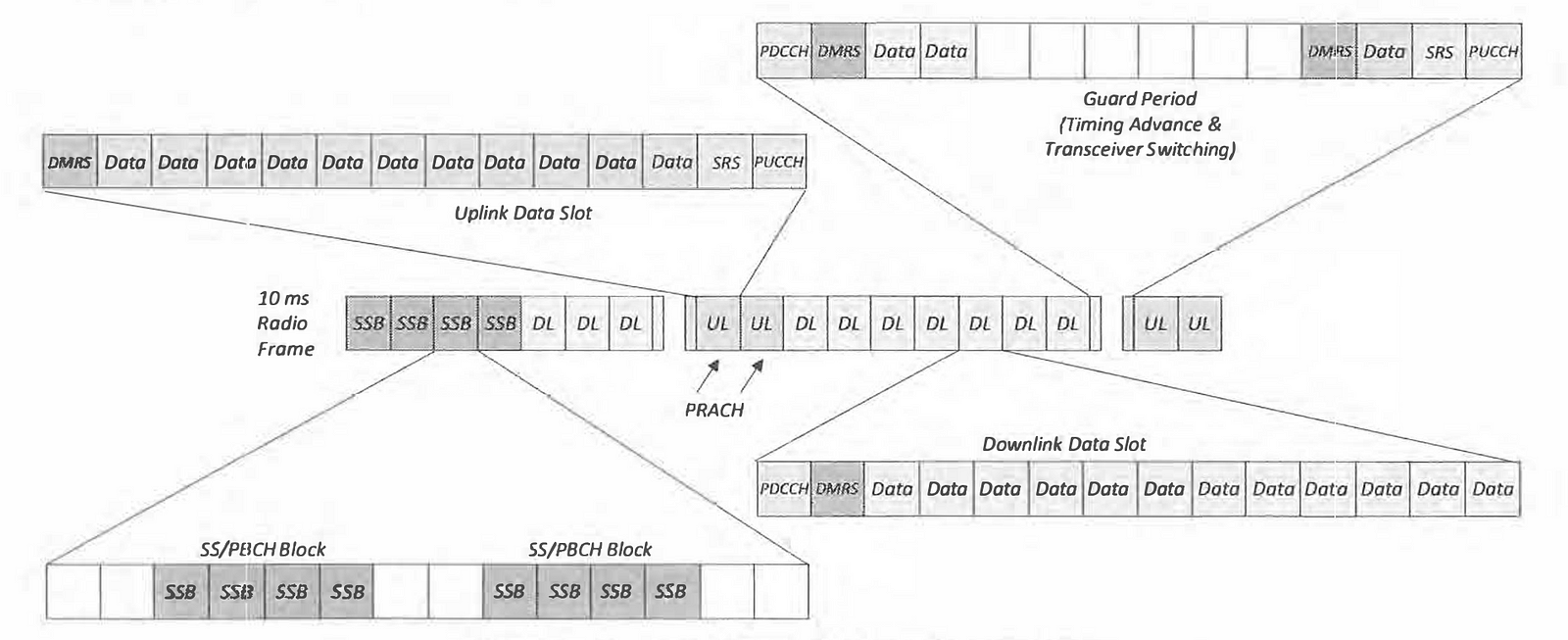
- This Slot Format starts with a series of 7 downlink slots. Upto 4 of these downlink slots can be used by the SS/PBCH, i.e. 1 slot is able to accommodate 2 SS/PBCH Blocks, and Frequency Range 1 supports up to 8 SS/PBCH Blocks (equivalent to 8 beams). Digital beam forming allows one beam to be transmitting the SS/PBCH while another beam is transferring data. Thus, the allocation of4 slots to the SS/PBCIH does not mean that those 4 slots cannot be used to transfer data. If the SS/PBCH has a 10 ms period, the SS/PBCH slots will be present at the start of every radio frame. The overhead generated by the SS/PBCH can be reduced if the 1transmission period is increased. However. this can increase latency when accessing a cell or when completing measurements.
- The Slot Format then includes a single slot which is allocated primarily for transceiver switching and timing advance. This slot includes a series of 4 downlink symbols, 6 guard period symbols and 4 uplink symbols. The downlink and uplink symbols within this slot can be used for data transfer although the capacity is relatively low when compared to a normal slot.
- The Slot Format includes 2 uplink slots at the end of each 5ms cycle.The uplink slots must accommodate the PRACH with a period which is determined by the PRACH Configuration Index.
Downlink
- The downlink throughput can be estimated by quantifying the throughput per slot and then averaging overtime. Start by considering a downlink data slot which is assumed to have 12 symbols available to the PDSCH after allocating the first symbol for the POCCH and the second symbol for the PDSCH DMRS. In this example, it is assumed that the POSCH is not frequency multiplexed with the DMRS so data is not transferred using the second symbol.
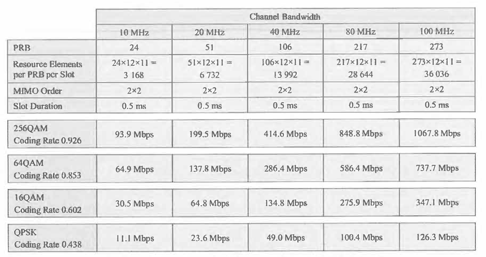
- Table below quantifies the downlink throughput associated with a downlink data slot. Figures are presented for a range of channel bandwidths and a range of coverage conditions (corresponding to CQI values of 15, 11, 6 and 3). 2x2 MIMO is assumed for this example so there arc 2 parallel streams of data towards the UE. The 30 kHz subcarrier spacing is assumed so the slot duration is 0.5 ms.
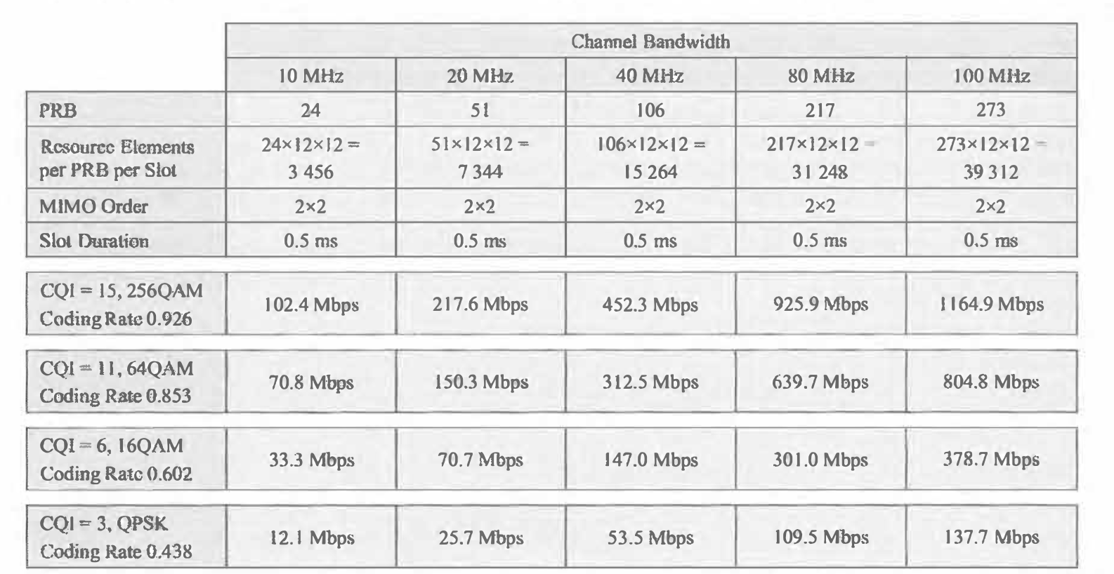
- The throughput figures for the 100MHz channel bandwidth illustrate that high throughputs can be achieved even when the radio conditions are relatively poor, i.e. over 130 Mbps is achieved when using QPSK with a coding rate of 0.438. The 20 MHz figures are comparable to those which can be achieved by LTE when assuming 1 symbol is allocated to the LTE PDCCH
- Table below quantifies the downlink throughput associated with the downlink symbols within a transceiver switching slot. It is assumed that 2 symbols are available to the PDSCH after allocating the first symbol for the POCCH and the second symbol for the PDSCH OMRS. The calculations are the same as those within Table above except that 2 symbols are available rather than 12 symbols.
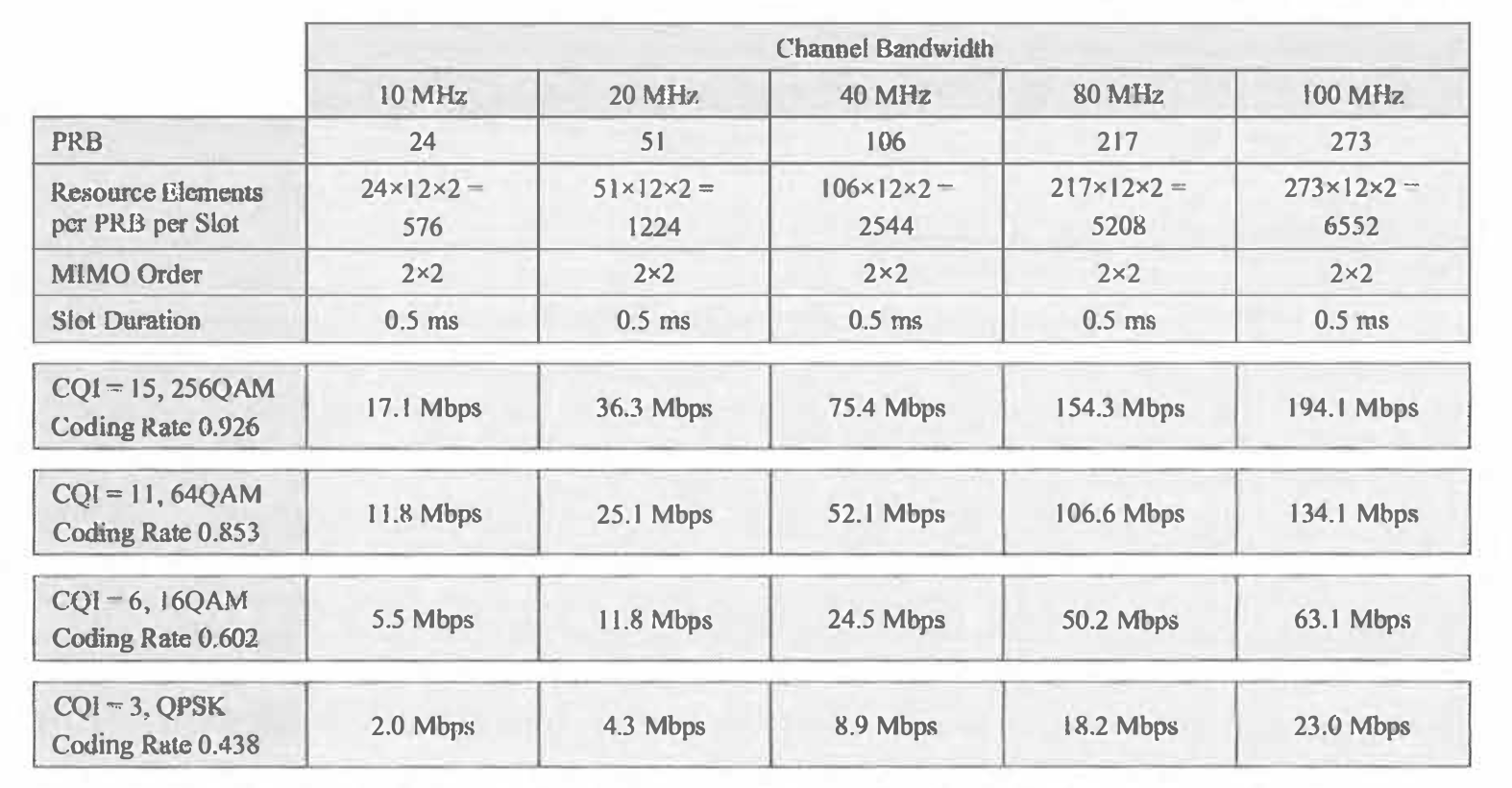
- The longer term average throughput can now be calculated as a weighted average of the figures within 2 Tables above. For example, if it is assumed that downlink data is not transferred during the slot which accommodates the SS/PBCH Block and that the SS/PBCH Block has a period of IO ms then the average throughput for the I 00 MHz channel with CQI = 15 can be calculated as
[( I I 64.9 x 13) + (194.1 x 2)] / 20 = 776.6 Mbps.
- Alternatively, if the SS/PBCH Block is assumed to have a period of 20 ms then the equivalent result is [(1164.9 x 27) + ( 194.1 x 4)] / 40 = 805.7 Mbps
- Table below presents the longer term average throughputs for each combination of channel bandwidth and radio conditions. Results are provided for both the 10 ms and 20 ms SS/PBCH Block periods. These figures can be interpreted as either an end-user connection throughput or a cell throughput assuming Multi-User MIMO is disabled. In reality, it is unlikely that the CQl = 15 result would correspond to an average cell throughput because it is unlikely that average radio conditions would allow an average CQI = 15.
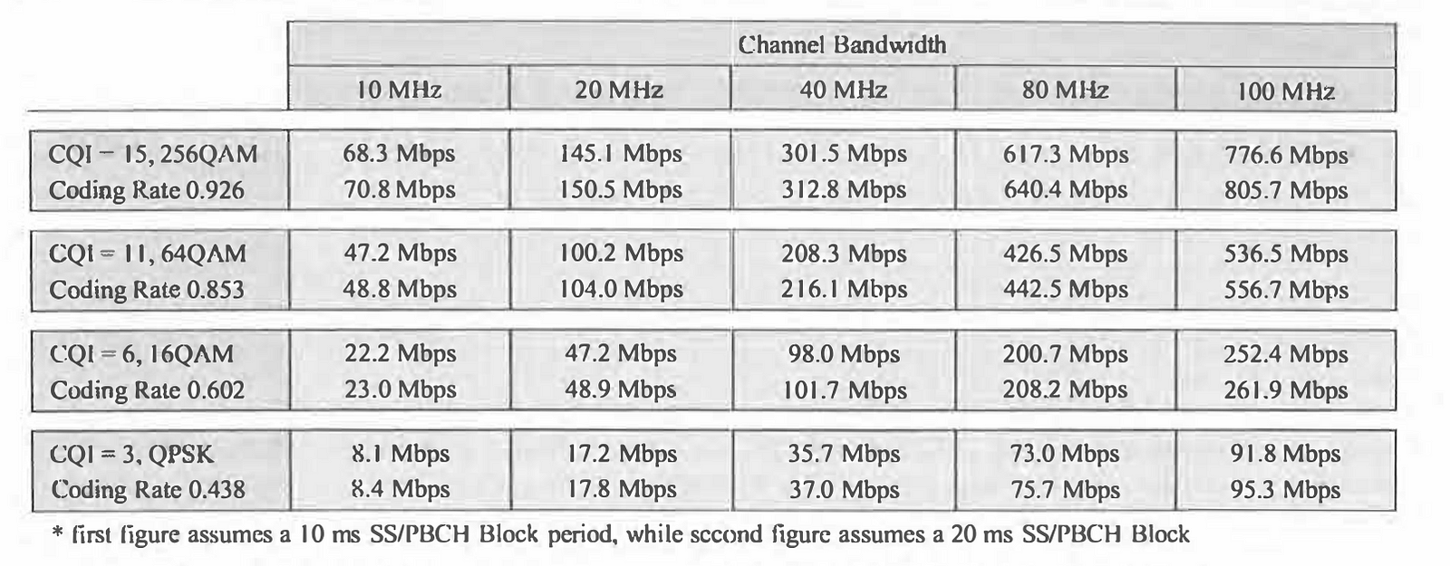
- In the case of cell throughput, Multi-User MIMO has the potential to increase the figures presented in Table 359. Operating bands within Frequency Range 1 support up to 8 SS/PBCH Blocks allowing up to 8 SS/PBCH beams. In theory, these 8 beams can be used to simultaneously transfer downlink data towards 8 UE, generating a total of 16 streams when all 8 UE are using 2x2 MIMO. This Multi User MIMO scenario would ideally increase the figures in Table 359 by a factor of 8. In reality, the increase would be less than a factor of 8 if it is assumed that a double symbol DMRS is used rather than a single symbol DMRS when allowing Multi-User MIMO with a relatively large number of UE. In addition, it is unlikely that Multi-User MfMO will be able to continuously spatially multiplex 8 UE. The number of UE which can be spatially multiplexed will depend upon the number of VE loading the cell and the geographic distribution of those UE across the cell area.
- The calculations presented above have ignored the over heads generated by the CSI Reference Signal, Tracking Reference Signal and Phase Tracking Reference Signal. They have also assumed that no additional DMRS symbols have been configured. The CSI Reference Signal for Beam Refinement can be frequency multiplexed with the SS/PBCH Block. This means that no additional overhead is required because the slot which accommodates the SS/PBCH Block has already been excluded from transferring downlink data. The overheads generated by the remaining Reference Signals can be included once their configurations are known. For example, a Tracking Reference Signal may occupy 3 Resource Elements per Resource Block in the frequency domain, and 4 symbols every 80 ms in the time domain. Based upon the previous example, the corresponding overhead relative to the total number of downlink data Resource Elements is given by (3 x 4) I [(I2 x 12 x 13 x 8) + (12 x 2 x 2 x 8)] = 0.08 %, i.e. the overhead generated by a single Tracking Reference Signal is small.
Uplink
- Similar to the downlink, the uplink throughput can be estimated by quantifying the throughput per slot and then averaging overtime. Start by considering an uplink data slot which is assumed to have 11 symbols available to the PUSCH after allocating the first symbol for the PUSCH DMRS and the last two symbols for the SRS and IPUCCH. In this example, it is assumed that the PUSCH is not frequency multiplexed with the DMRS so data is not transferred using the first symbol.
- Table below quantifies the uplink throughput associated with an uplink data slot. Figures are presented for arrange of channel bandwidths and a range of coverage conditions (assuming the same coding rates as were used for the downlink calculations). 2x2 MIMO is assumed for this example so there are 2 parallel streams of data towards the Base Station. The 30 kHz subcarrier spacing is assumed so the slot duration is 0.5 ms.
- The uplink figures in Table below are comparable to the downlink figures in Table above.The uplink figures are less than the downlink figures because it has been assumed that there arc only 11 symbols available to the PUSCH, while there are 12 symbols available to the PDSCH. Otherwise, the uplink and downlink calculations are the same. Figures for 256 QAM have been included for the uplink although this is an optional UE capability which is indicated by the UE using the pusch-256QAM information element.
- Table below quantifies the uplink throughput associated with the uplink symbols within a transceiver switching slot. It is assumed that only 1 symbol is available to the PUSCH after allocating the first symbol for the PUSCH DMRS and the last two symbols for the SRS and PUCCH.
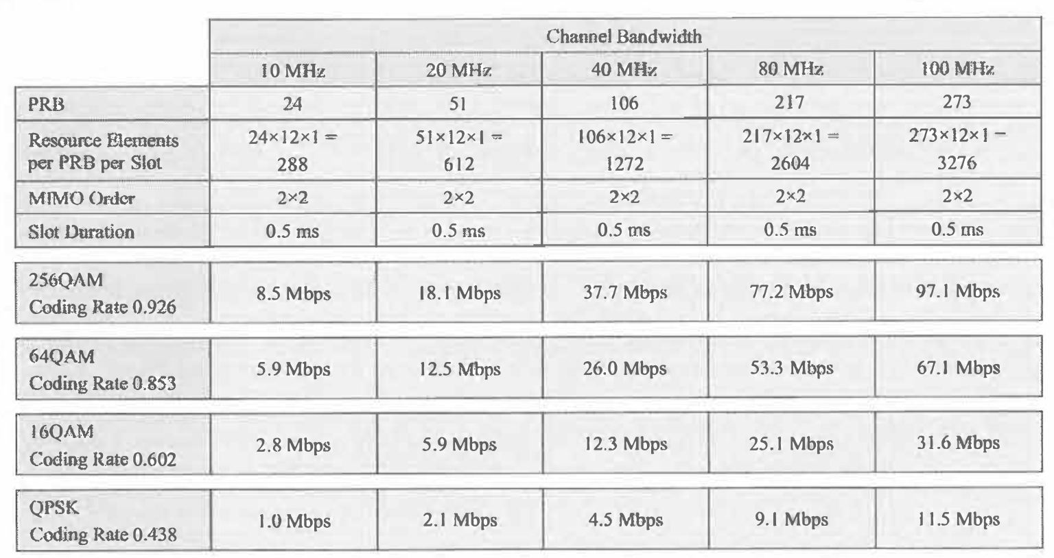
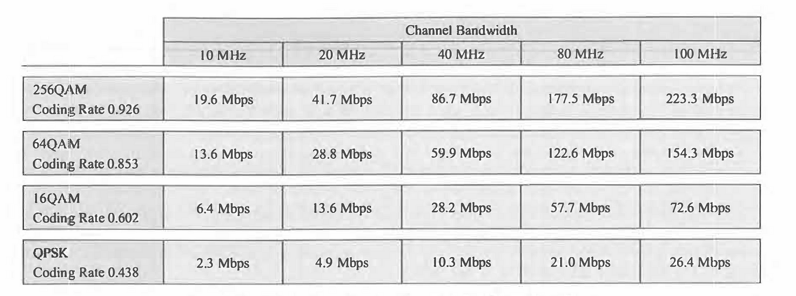
- Similar to the downlink, the longer than average throughput can now be calculated as a weighted average of the figures within Table 360 and Table 361. For example, the average throughput for the I 00 MHz channel with 64 QAM and a coding rate of0.853 can be calculated as [(737.7 x 4) + (67.1 x 2)] / 20 = 154.3 Mbps
- Table below presents the longer term average throughputs for each combination of channel bandwidth and radio conditions.These figures can be interjected as either an end-user connection throughput or a cell throughput assuming Multi-User MIMO is disabled. In reality, it is unlikely that the 256QAM result would correspond to an average cell throughput because it is unlikely that average radio conditions would allow 256QAM
- In the case of cell throughput, Multi-User MIMO has the potential to increase the figures presented in Table below. Operating bands within Frequency Range 1 support up to 8 SS/PBCH Blocks allowing up to 8 SS/PBCH beams. In theory, these 8 beams can be used to simultaneously receive uplink data from 8 UE, generating a total of 16 streams when all 8 UE arc using 2x2 MJMO. This Multi-User MIMO scenario would ideally increase the figures in Table below by a factor of 8. In reality, the increase would be less than a factor of8 ifit is assumed that a double symbol DMRS is used rather than a single symbol DMRS when allowing Multi-User MIMO with a relatively large number of UE. In addition, it is unlikely that Multi-User MIMO will be able to continuously spatially multiplex 8 UE. The number ofUE which can be spatially multiplexed will depend upon the number ofUE loading the cell and the geographic distribution of those UE across the cell area.
- The calculations presented above have ignored the overheads generated by the PRACH and the Phase Tracking Reference Signal. They have also assumed that no additional DMRS symbols have been configured. The overhead generated by the PRACH depends upon the PRACH Format and the number of PRACH occasions within a specific time window. This means that a long PRACH Format can be used to help maximise the supported cell range. PRACH Format 0 occupies 1 ms in the time domain and 3 Resource Blocks in the frequency domain (based upon the PUSCH using a 30 kHz subcarrier spacing). If the PRACH Configuration Index is selected to allow 1 PRACH occasion per 10 ms Radio Frame, then the PRACH occupies 3 x 12 x 14 x 2 = 1008 Resource Elements per Radio Frame.
- Table below presents the over head generated by the PRACH relative to the total number of Resource Elements available to the PUSCH for the transfer of uplink data. These calculations assume that the PRACH occupies I I symbols per slot rather than 114 symbols per slot because the PUSCH is able to use 11 symbols per slot, i.e. from the perspective of the PUSCH, 11 symbols arc lost rather than 14 symbols.
- The overheads presented in Table below would increase if the number of PRACH occasions per Radio Frame increases, e.g. PRACH occasions could be time multiplexed across the two pairs of uplink slots, or frequency multiplexed within a single pair of uplink slots. Alternatively, the overheads would decrease if the PRACH occasions occur less frequently, e.g. 1 PRACH occasion per 20 ms rather than 1PRACH occasion per 10 ms.

Conclusion
Effective 5G network planning is crucial to maximizing the performance and reliability of next-generation mobile networks. By carefully allocating gNB and Cell Identities, defining RAN Notification Areas, and planning Tracking Areas, network operators can enhance user experiences while managing signalling and paging loads efficiently. As 5G technology continues to advance, the principles outlined in this guide will serve as a foundation for optimizing network infrastructure and ensuring robust, scalable communication systems that meet the demands of an ever-connected world.
References
- 4G 5G Testing and protocol analysis
- Syllabus for 4G 5G Protocol Testing Training
- Contact Us for training
- Qualcomm Academy Videos
- 3GPP Website
- ShareTechNotes


Comments
Post a Comment